

FV-5 Phase Model (Clamping Force Curve)
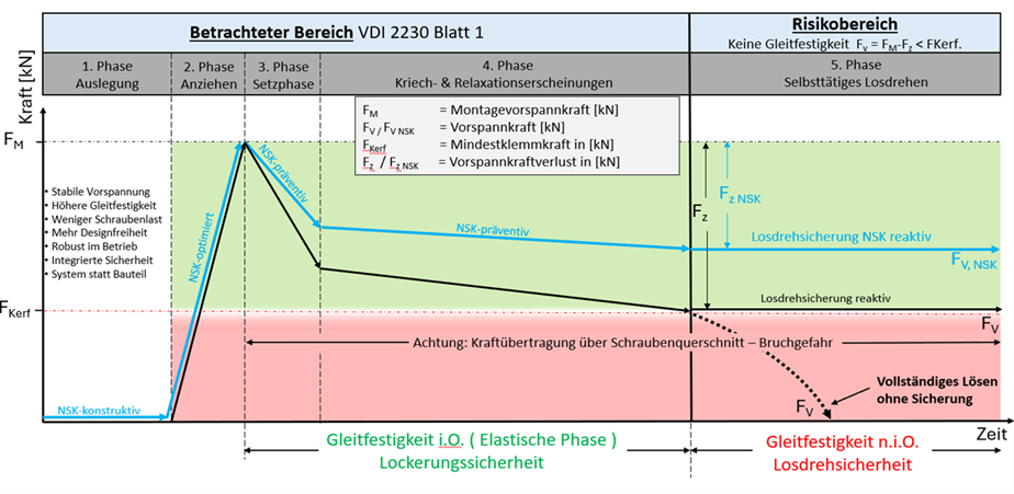
The goal of the model is to fully capture the physical mechanisms—from design through to potential loosening—in causal order and to make them controllable through design.
The five phases are:
- Design
- Tightening and Assembly Phase
- Settling Phase
- Creeping and Relaxation Phase
- Loosening Phase
Phase 1 – Design: Definition of System Compliance
During the design phase, the functional and economic constraints are defined. More than 80% of the subsequent costs and functional reliability are determined during this phase.
Basic Mechanical Principle
The bolted joint is modeled as an elastic two-spring system in accordance with VDI 2230 Sheet 1:2015-11:
- Screw spring stiffness cS
- Clamping part stiffness cK
The force distribution factor is:
Φ = c S c S + c K
Additional elastic resilience reduces cS or increases the total compliance. This reduces the force transfer factor Φ.
Consequence: The additional bolt load during operation is reduced.
Consideration of spring-like fasteners
Effective spring-like elements with reproducible residual spring force according to DIN 267-26:2005-12 are often not explicitly taken into account in conventional calculations.
If these elements are incorporated into the calculations, the following results occur:
- lower additional bolt load
- more stable preload force
- increased slip resistance
- a delayed transition to the loose rotation phase
- robustness against settlement losses
Design potential
The increased system flexibility allows for:
- Cross-section and weight optimization
- Reduction in bolt size while maintaining the same functional reliability
- Cost advantages at the assembly level
The design thus proactively ensures stability over the entire life cycle.
Phase 2 – Tightening and Assembly Phase
The assembly defines the actual initial preload force FV0
During tightening, a defined torque is applied, which is converted into a preload force (Fv) through friction at the thread and between the head and nut. The preload force curve shows a rapid increase until the target value (torque or angle limit) is reached.
Physical focus: Relationship between tightening torque, friction coefficients, and resulting clamping force.
Characteristic: Ideally, an approximately linear, or possibly slightly nonlinear, rise in the Fv curve.
This phase defines the initial state for all subsequent changes in the preload force.
The following factors are crucial:
- uniform surface pressure in the compression cone
- reproducible coefficient of friction window
- controlled tightening procedure (torque, angle of rotation, or a combination)
The preload force is calculated as follows:
F V = M A d 2 ⋅ μ thread + μ head
Variations in the coefficient of friction dominate the variation in preload force.
Elastic elements play a supporting role here:
- more uniform force distribution
- reduction of local stress peaks
- stabilization of the initial preload force
The elastic operating phase begins upon completion of assembly.
Phase 3 – Setting Phase
The settling phase begins as soon as the fasteners are tightened. During this phase, plastic adaptation processes occur in all zones responsible for force distribution in the bolted joint. The goal is to form contact surfaces capable of bearing the actual load—accompanied by an unavoidable initial decrease in preload.
Physical Causes of Embedding
Embedding is not a prolonged process, but rather a predominantly short-term plastic adaptation process. It results from:
- plastic leveling of microscopic roughness peaks,
- microdeformations in the head and nut seating areas as well as in the interface surfaces,
- local material flow due to high contact pressures in the compression cone,
- microscopic relative slip under tangential loading.
These mechanisms lead to an effective shortening of the clamping length. Since the screw is elastically stretched, any shortening immediately results in a reduction of the loss of preload.
Factors influencing loss of preload
The magnitude of the settlement-induced loss of preload Δ F Z depends significantly on:
- the surface properties (roughness, coating, hardness),
- the material pairing of the contacting surfaces,
- the magnitude of the assembly preload (contact pressure),
- the geometry and stiffness of the interface surfaces,
- the number and location of the joints in the force path.
Particularly critical factors include short clamping lengths, soft materials, or multiple interface surfaces, as the relative influence of a given settlement displacement is greater in these cases.
Characteristics of the Settlement Phase
The settlement phase is characterized by:
- a brief, often abrupt loss of preload immediately after assembly,
- the dominance of plastic processes (clearly distinct from time-dependent creeping or relaxation),
- high safety relevance for slip resistance, sealing function, and long-term durability.
Mechanically, the loss of preload can be described in simplified terms as follows:
ΔF Z = c total ⋅ Δs
where
Cges = total spring stiffness of the system
ΔS = resulting settlement
The greater the total elastic compliance, the smaller the relative loss of preload for the same settlement.
Significance for functional safety
The settling phase often determines whether the connection remains permanently slip-resistant. If the minimum clamping force is not maintained even in this early phase, a latent risk of loosening arises under dynamic loading.
The design countermeasure therefore does not consist of “over-tightening,” but rather in specifically increasing the system compliance so that settlement can be elastically compensated.
The settling phase is thus not a side effect of assembly—it is the first test of the design.
Mathematical treatment (VDI 2230, in brief):
- Settling travel reserve: Increase in elastic elongation through an adapted tightening procedure.
- Increase in resilience: Application of various countermeasures, including the use of spring-loaded fasteners to reduce relative Fv loss.
Phase 4 – Creeping and Relaxation Phase
This phase is time-dependent and material-specific.
Relaxation
Stress reduction at constant elongation due to:
- Microplasticity
- Viscoelastic flow
- Contact stress redistribution
Occurs over weeks to months.
Creeping
Slow plastic elongation under constant stress due to dislocation motion in the crystal lattice. Occurs over years.
Both effects continuously reduce the prestress.
Spring elements slow this decline:
- Residual spring force has a compensating effect
- The minimum clamping force remains above the yield point for a longer period
- The transition to Phase 5 is delayed
Objective: Stabilization of the preload force through the system’s elastic resilience
Elastic resilience describes the sum of all reversible elastic deformations in the direction of force flow and is decisive for the joint’s ability to compensate for changes in preload resulting from embedding, relaxation, or temperature.
Contributions to the total yield (δges):
- Longitudinal elongation of the screw,
- elastic compression of the clamping parts,
- spring effect of additional fasteners (tension washers, residual spring force washers, NSK® washers),
- elastic deformation in the area where the head and nut contact the surface.
δges = δ screw + δ components + δ spring element
The larger δges is, the more elastic energy can be stored, and the smaller the effect a given embedding or relaxation displacement has on the remaining preload force. In this context, spring elements act as mechanical energy reservoirs.
Effects on the preload force curve (abridged):
- lower preload force drop under embedding, relaxation, and temperature loads,
- more stable clamping force under dynamic and thermal stress,
- improved slip resistance and increased resistance to loosening,
- extended lifetime of the joint.
For electrical screw connections, increased resilience also leads to more stable contact pressure and reduced fluctuations in contact resistance.
Normative integration (compact):
VDI 2230 as well as standards such as DIN 267-26, DIN EN 16984, and DIN EN 17976 enable the computational and experimental determination of the spring effect and thus the targeted design of the overall compliance.
Phase 5 – Start-up Phase
The loosening phase begins when:
F V < F ( K , min )
and dynamic transverse loads occur simultaneously.
If the frictional force in the thread falls below the induced reverse torque, a self-induced rotational movement begins. This has been experimentally verified in DIN 65151:2002-08 and DIN 25201-4:2021-12
Self-acting loosening by rotation is a rotational movement of the screw or nut in the direction of loosening that occurs without a direct external torque and leads to a critical loss of preload force. According to DIN 25201-4, this condition occurs only when:
- the preload force drops below the required minimum clamping force (loss of sliding resistance) and
- dynamic transverse loads act that exceed the frictional forces in the joint, head contact, and thread.
The loosening phase thus describes the transition from still reversible relative rotational movements to the irreversible loss of function of the bolted joint.
Prerequisites (summarized):
- Failure to maintain the minimum clamping force: due to embedding, relaxation, or special load cases.
- Dynamic transverse loading: e.g., vibration, impact, coupling processes.
- Friction forces in the head, joint, and thread contacts falling below the required level → loss of self-locking.
Sequence of loosening (abbreviated four-step overview):
- Step 1 – Start of relative rotational movement: Slipping on the interface surface, constant friction force, elastic bending of the screw, process still reversible.
- Step 2 – Thread slippage: Oscillation of the screw thread within the nut thread, reduction in transverse stiffness, tilting of the screw head.
- Step 3 – Critical condition for loosening: Transition from translational slip to rotation; uneven surface pressure; torsional stresses and pitch moments take effect; onset of initial rotation with Fv already reduced.
- Step 4 – Complete loosening: Slipping of the screw head, release of elastic torsion, self-acting loosening by rotation in the direction of loosening, loss of function of the screw connection.
Consequences
With the loss of clamping force, load transfer increasingly occurs via shear and hole friction, which significantly increases the risk of screw breakage, component damage, and sudden functional failure.
Protection against self-acting loosening by rotation:
VDI 2230 clearly stipulates that fasteners must be designed to be slip-resistant. According to DIN EN 17976, securing elements must be used whose effectiveness must be verified in accordance with DIN 25201-4 (e.g., wedge-locking washers, profiled washers, NSK® washers). Falling below the minimum clamping force—even when a securing element is used—means that part of the operating force is transmitted through the screw cross-section. As a result, part of the operating force is transmitted through the screw cross-section. Possible consequences include screw failure or damage to the assembled components.
The key protective mechanism remains maintaining slip resistance through sufficient preload and resilience.
Preventive and reactive locking strategies
Preventive
Increase in elastic resilience:
- lower force transmission factor
- more stable preload force
- higher slip reserve
Multifunctional securing elements are effective:
- preventively against loosening
- reactively against unscrewing
Key message
The bolted joint is not a static component, but a time-dependent elastic system. Its functional reliability is not determined only in the event of failure, but rather during the design phase through the targeted adjustment of the system’s compliance.
The five-phase model makes this life cycle mechanically explainable and structurally controllable.
1. Role of multifunctional screw securing elements (compact)
Multifunctional securing elements (e.g., NSK® washers) combine:
- Increased resilience—stabilization of the preload force and reduction of the transition to critical loosening conditions.
- Mechanical locking effect against rotation—e.g., via wedge action, profiling, or increased coefficients of friction.
Thus, they act preventively against slackening and reactively against self-acting loosening by rotation, without, however, replacing the need to maintain sufficient clamping force. Normative references are provided in VDI 2230, DIN EN 17976, and DIN 25201-4 (test methods).
2. Conclusion – Specific Benefits of the FV–5-Phase Model
Compared to a purely static analysis of the preload force, the FV–5-phase model offers the following key advantages:
- Holistic life-cycle analysis:
The preload force curve is described not as a one-time state, but as a time-dependent process ranging from tightening through embedding and elastic stabilization to possible loosening. - Clear separation of the mechanisms of action:
Plastic settlement processes, elastic resilience, and loosening effects are physically differentiated and assigned to specific defined phases. This facilitates the targeted selection of design and computational countermeasures. - Compatibility with standards:
The model is compatible with the requirements and verification procedures specified in VDI 2230, DIN 267-26, DIN EN 16984, DIN EN 17976, and DIN 25201-4 and can be used as an interpretive framework for classifying normative requirements. - Foundation for resilience and safety concepts:
By explicitly capturing settlement, resilience, and loosening behavior, the model establishes the basis for understanding screw safety as resilience—including the ability to derive corresponding characteristic values. - Support for the design of multifunctional securing elements:
The role of spring-like and locking elements can be specifically evaluated in each phase (settlement compensation, increased compliance, anti-loosening).
Overall, the FV–5-phase model enables a systematic, standards-compliant, and practical description of the preload force curve, providing an expanded basis for design, validation, and safety assessment for both mechanical and electrical bolted joints.